

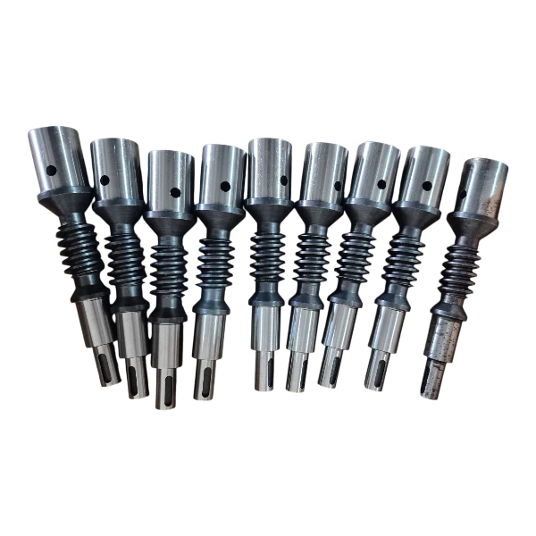
How a worm gear mechanism works
In its common arrangement, a worm mechanism transfers motion between non-intersecting, perpendicular axes. The screw-shaped worm meshes with the wheel; the ratio depends on the wheel tooth count and the number of worm starts. Gearboxes, positioning mechanisms and low-speed drives are among its applications.
- Number of worm starts, wheel tooth count and helix hand
- Module, centre distance and mounting references
- Input speed, load, duty cycle and lubrication
Matching drawing and mounting data
The worm and wheel drawings must be consistent with each other. Bore, shaft, keyway and bearing surfaces determine their positions within the housing. Clearly defining the backlash to be adjusted during assembly and the references to be inspected establishes a clearer link between component manufacture and system assembly.
| Topic | Required data | Selection assessed |
|---|---|---|
| Ratio | Starts and tooth counts | Reduction ratio |
| Layout | Centre distance and axes | Housing compatibility |
| Material | Mating surfaces and load | Wear behaviour |
| Operation | Speed and lubrication | Thermal conditions |
Sliding, material and lubrication
Requesting a quotation for a worm gear pair
Frequently asked questions
Is a worm drive always self-locking?
No. Backdriving behaviour depends on worm geometry, friction, load and lubrication conditions. Self-locking must not be assumed where a load needs to be held safely; a brake or suitable holding mechanism should be assessed separately in the system design.
Should the worm and worm wheel be assessed together?
Yes. Module, number of worm starts, wheel tooth count, helix hand and centre distance determine compatibility. If an existing mating part is to remain in use, its geometry and wear condition must also be included in the assessment.
What operating information is needed for a quotation?
Alongside the drawing and quantity, provide input speed, required ratio, load, duty cycle and lubrication details. Whether motion is continuous or intermittent, together with the mounting orientation, helps define the manufacturing scope.